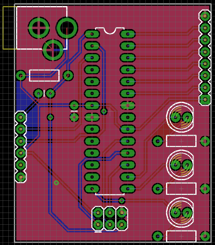

- Eagle schematic design manuals#
- Eagle schematic design update#
- Eagle schematic design full#
- Eagle schematic design software#
- Eagle schematic design Bluetooth#
Eagle schematic design Bluetooth#
Besides, with the help of on-board ESP32 chip, the SEA board also enables your Arduino with WiFi and Bluetooth function.It consists of two development boards, the Ethernet board A and the PoE board B, The Ethernet board contains Bluetooth / Wi-Fi dual-mode ESP32-WROVER-E module and IP101GRI, a Single Port 10/100 Fast Ethernet Transceiver (PHY). ESP32-Ethernet-Kit: ESP32-Ethernet-Kit is an ESP32-based development board produced by Espressif.In this episode, we review the schematic for the HUZZAH Feather ESP32 by Adafruit Directions Review the embedded schematic below Open this link to take a peek at the hardware the schematic represents Develop a short list of questions about the schematics that you would like clarified.

Eagle schematic design update#
Blowing an ESP32 Fuse! Trimble Thunderbolt Monitor Mega Update v1.1.0 and v2.0.0! Talk: 3D Printing for the Radio Amateur RSGB. Where Is The Eagle Component Library For 0 1 Breakaway Headers Electrical Engineering Stack Exchange Using Eagle Schematic Learn Sparkfun Com Github Codm Eagle Libraries Loose Collection Of Our Self Made Eagle Libraries Ajouter Une Nouvelle Librairie De Composants Sur Eagle Ajouter Une Nouvelle Librairie De Composants Sur Eagle.The picture below shows an ESP32-WROVER module with a PCB antenna. ESP32-WROVER-B and ESP32-WROVER-IB have PSRAM that operates at 3.3 V and supports up to 133 MHz clock rate. ESP32-WROVER (PCB) and ESP32-WROVER (IPEX) have PSRAM that operates at 1.8 V and supports up to 144 MHz clock rate.1355 Topics 5971 Posts Last post by adafruit_support_bill Tue 3:40 pm.Here is a useful, simple and tested Arduino voltmeter circuit which can safely measure input DC voltages from 0V to 30V, including 12V.Users who have contributed to this file 581 lines (576 sloc) 32.7 KB Raw Blame.It will work with a 12V power supply and will have bass, treble, and mid-frequency control so that the output audio can be adjusted as required In this project we design an active Tone control circuit powered by an op-amp with a PCB design.Route multi-layer boards with support for copper pours and DRC. Design multi-sheet schematics with our fast and easy-to-use wiring tool. These strips serve to connect multiple components together without wire, and can be separated, as pictured, into smaller segments with a few twists of a drill bit (see “Breaking Stripboard Traces” below). On stripboard there are parallel strips of copper that run the length of the board, connecting the holes together. I'm moving from using a NodeMCU as a prototyping board to putting an ESP12E/F on my own PCB.

The github has several Altium files, which may be what I need.
Eagle schematic design full#
I'm looking for the full NodeMCU schematic.
Eagle schematic design manuals#
Eagle schematic design software#


 0 kommentar(er)
